My initial approach to generate floor plans in Rhino + Grasshopper was to divide a given perimeter into containers, and pack them with satisfying combinations of rooms. Researching tiling and bin packing has helped greatly, along with methods in computational geometry. A reductive approach has been very helpful in the preliminary stages of space planning, but much work is yet to be done to refine the algorithm so that a working floor plan is created.
I am exploring the tiling of a rectangle, and dividing a rectangle given the placement of 1+ rooms into the space. Given some perimeter, the algorithm tiles the space with horizontal or vertical chords, which divides the remaining area. Every possible rectangle that can be drawn with the divisions becomes a container to be packed.
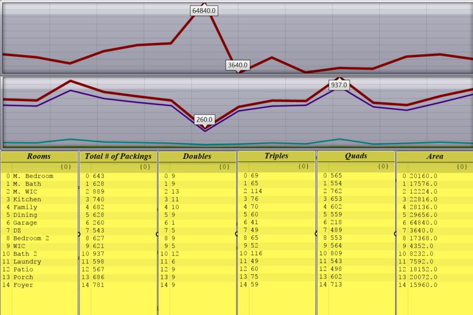
Each container can be packed with some number of rooms. Sometimes the containers are too small or too large to pack any rooms, and other times it can pack many. This depends on the relationship between the container dimensions and the range of room dimensions. For a given program of 15 rooms (see below), it can also be seen how the sizes of the rooms (top graph) affect the number of packings (bottom graph). The garage is the largest and also has the fewest number of possible packings, while Bath 2 seems to be the most optimally sized to be packed. Since a packing of 2 (Double) is a sub condition of every packing up to 4, the number of Doubles for a given room greatly affects the overall packability. Bath 2 and M. WIC have the highest # of packings because they can form alignment with the most combinations. Finding these types of trends could guide the algorithm in deciding how to best reach a full packing.
The tiling and packing workflow could also be applied to the placement of showers, cabinets, furniture, appliances within certain rooms, exploiting the self similarity of how rectilinear shapes fit together. Initially placing a few rooms constrains the number of possibilities, as does drawing the perimeter with 6, 8, 10+ sides; these constraints help to cut the number of possibilities down. Some limitations of the algorithm can be alleviated by the requirement that the designer intervenes.
Below, the definition shuffles through the combinations to generate full plans and analyze them for adjacency satisfaction. It takes a few minutes for it to process all of the packings for the containers, but then the search begins to find the combination that satisfies the most conditions. Some container combinations result in an unpacked space, which I haven’t filtered out yet as they could be used as extension space for any surrounding room.
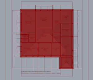
In the animations above, some rooms are placed in constant locations, and the remaining space is then packed with the remaining rooms. This method is not fully autonomous, but can get to a point that Galapagos begins to run through floor plans and tries to converge to a minimum fitness number. I have used geometric computation methods to find combinations, appreciably speeding up the process. From the given conditions, a profile is built and is used like a road map. The profile (a collection of graphs) provides a shortcut to combinations that fit into rectangles of particular sizes.
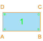
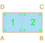
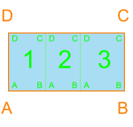
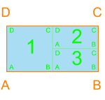
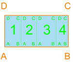
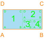
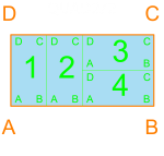
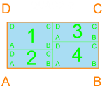
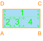
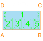
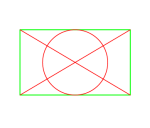
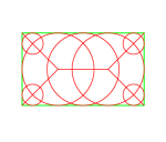
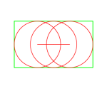
Below is an introduction to some basic configurations. I have become very familiar with the different ways that 1, 2, 3 and 4 rectangles can fit perfectly within a container. At 5 rectangles the number of possible configurations grows tremendously, which is great for diversity but not for processing time. Dividing the containers small enough for combos of 2, 3, and 4 rectangles is important to ensure that the algorithm has a chance of packing all of the containers. This packing method allowed me to constrain the perimeter. The orange outline and text corresponds to the container, and the blue w/ green rectangles correspond to rooms with dimensions that would allow for such a configuration.
It is more common in urban conditions to have geometric constraints, particularly for the perimeter, therefore the aforementioned method is more applicable for projects with more constrained perimeters. In more rural or suburban conditions, the dwelling stands alone and has more flexibility, occasionally resulting in greater variation to the perimeter. Here is an example of a relatively high valued (monetarily) home in Iowa:
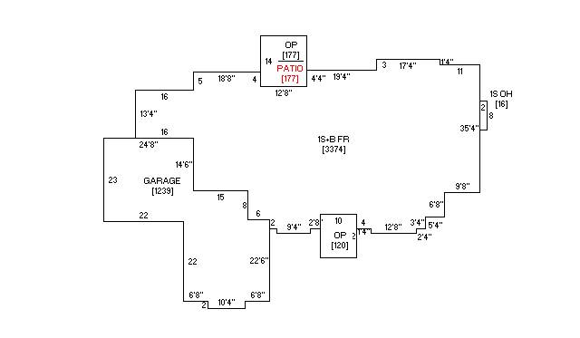
Either through bay windows or bumping out a room from the perimeter, I often see this organizational type. It is usually more expensive for each variation in the perimeter because of the additional work needed for the foundation, walls, and roofing, due to the added needs in design, materials, and construction. Each offset should always be a masonry dimension, standardizing designs to discrete 4″ increments. A different floor-planning methodology might be needed to generate this type of plan where the rooms influence the building form, rather than conforming to a given perimeter.
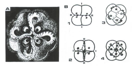
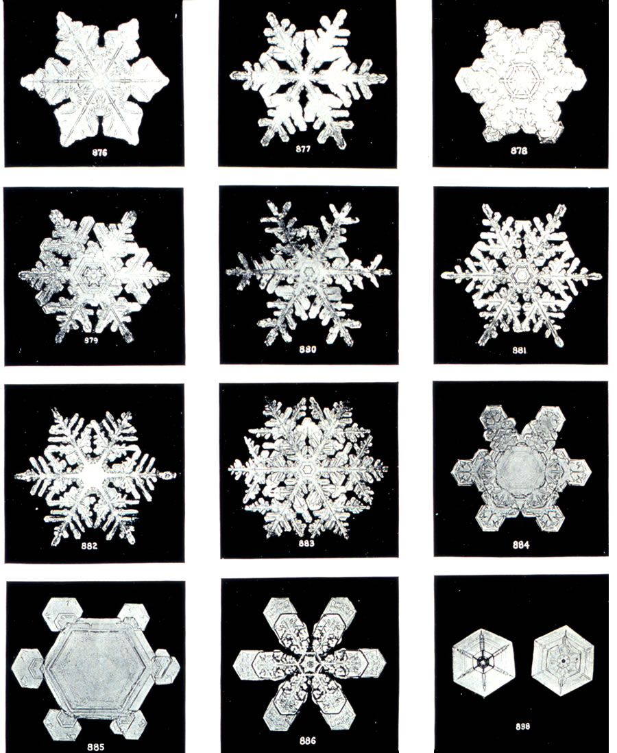
Architecture is not simply about rectangles fitting inside of larger rectangles, nor just space planning itself, but this reductive approach is an attempt to simplify the conditions so that the program may be easier to define and possible to calculate. After finding satisfying relationships between simple geometries, I hope to graduate to more complex organizational structures and allow for transformations to the rectangular spaces. I am continuously looking for inspiration from existing architectural typologies, mathematical structures, and structures found elsewhere in nature. Fractals, molecules, organisms, and crystalline forms that occur naturally are geometric inspirations that I hope to apply to this method of generative design. Nature’s Operating Instructions: The True Biotechnologies has been a wonderful guide in gleaning knowledge from nature’s design laboratory. Humans are part of nature, rather than separate or above it, and this admission is important for sustainable design.
/K.Kovar/Figure%201.gif)
Having an idea for a program, and then executing all of the necessary functions of that program are very different. A consistent and efficient data structure is vital. I am becoming more comfortable with datatrees and graphs, but hopefully with time I can apply them in the best way possible. I have recently been using Kangaroo in Grasshopper to form bubble diagrams that arrange through attraction / repulsion. This is not an exhaustive approach, but it is a more organic and responsive way of designing through an algorithm.
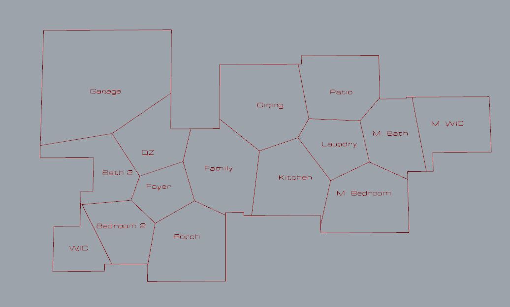
Creating forces between the spaces in a bubble diagram has been a tricky task. Although it would be fairly simple to setup forces between all spaces that MUST be adjacent to one another, absolute adjacency is not the only condition. There are a gradient of options for adjacency as can be seen in a different example program below:

Converting such conditions into forces with varying magnitudes is a challenge, and the number of possible configurations is very large. Given many constraints, there can still be many isomorphisms of a graph. I have been looking into different chemical and molecular models, such as many of those found on the University of Colorado’s PhET Interactive Simulations. The unique qualities of a design may come from how the more flexible conditions are still able to satisfy. Through such simulations, it may converge to a similar configuration each time, which may not be the most desirable. The simulation must converge, but it would be ideal to allow for the strength of the forces to change dynamically so that the exploration of configurations does not stagnate.
It seems like it would be simple, but slicing / morphing a bubble diagram into something that resembles a working floor plan is a rather difficult task, given the number of unique ways of going about it. There is a lot of useful information that can be taken from voroni diagrams and isovist samples, but there are times where there is fork in the road and it is difficult to decide how the algorithm should come to a decision. However, I think I am digging at core principles of spatial organization which has allowed me to form a more structured understanding and methodology.
I have found useful tools for Rhino and Grasshopper, and nearly all are free to use, or at least try out. I would not be able to do much without the great support of the Grasshopper community, and am very grateful for the following tools and the dedication of their creators: SpiderWeb by Richard Schaffranek, Syntactic by Pirouz Nourian and Samaneh Rezvani, Kangaroo by Daniel Piker, and Galapagos by David Rutten. I have also found the work of Reinhard König helpful and reinforcing. It is always great to find that there are people out there who are passionate about the same things. Luckily, all of the aforementioned developers and researchers are much further along this path and have been gracious enough to share their work, and I am very grateful.
Update:
Still pretty far off, but I developed a more sophisticated spring system for each room. I also made use of HoopSnake, creating a feedback loop and allowing the forces to be more dynamic. At first, the rooms are able to morph and rotate, but as the number of iterations grow, that freedom is constrained, creating a more orthogonal configuration. Further forces must be applied to fill in gaps, or transform the rooms themselves into rectilinear polygons. This may require defining a room as a set of smaller spaces of some resolution. There are times when the algorithm needs to still satisfy some conditions, so it flexes and tries to make it work but some rooms can get “trapped.” This is another problem that must be addressed, perhaps with rotational rather than linear forces. Further alignment, morphing, and snapping will hopefully get it closer to a recognizable and working floor plan.
Progress Update:
It is slowly getting better, but I want the adjacencies to all make sense before collapsing the rooms in so that each adjacent edge touches. I’ve needed to think more in terms of a timeline, which smaller checkpoints that would catalyze a change in all of the forces at play, i.e. machine learning. Some of the forces need to react similar to non-Newtonian fluids, where initial contact between rooms, as they are colliding, will do little to transform the shape of the room, but if the adjacency is desirable, and with enough passage of time, the room can flex within its acceptable range and meld into a perfectly adjoining position. Here is the reasoning behind the spring system:
The spring system tries to maintain the overall shape of the rectangle, but flexes under strong enough forces. I haven’t yet mastered the propagation of a force across the springs to both prevent deformation but allow some guided range of deformation, but hopefully with more time I will recognize how the data should flow. The purpose for using points and circles for the springs is because Kangaroo primarily uses points. Although Box Collisions are possible with Kangaroo, manipulation of spring behavior is an important aspect I want to develop. The work of Jeremy England of MIT resonates with me. Perhaps in future iterations I can incorporate a similar structure of work applied to the system, and understand the process as operating between hot and cold influences.