A part of computational design that interests me is eliminating, or minimizing, repetitive actions in a workflow. Something simple and frequent that I encounter in AutoCAD is a shift in a wall’s position; an inevitability. If additional drawings exist that are based on the position of walls, then all related drawings must be updated to conform to the changes. Rather than working with drawings that have line work that is disconnected, I prefer to work with and setup drawings that are interdependent, tied together with geometric and design logic.
Let’s declare the inputs and outputs of an algorithm to detect spaces:
Inputs:
- Walls & door headers
- User defined internal point per space
Output:
- Automatic detection of spaces (for purposes of area reporting, scheduling, reflected ceiling plans, floor pattern plans, etc.)
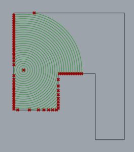
When creating a Hatch in AutoCAD, it is possible to select an internal point, whereby an algorithm attempts to find a closed boundary to fill. This is essentially the goal, but instead of a hatch, the region boundary is desired. As most of these problems start in my head, I underestimate the complexity because I am thinking too simply, and too continuous. My first inclination was to imagine a bubble forming at the internal point and expanding outward. Eventually the bubble would morph and collide with all boundary geometry.
Seems to work in my head, but more difficult to implement as an algorithm.
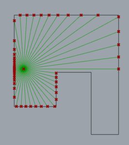
Similar to an expanding balloon, I thought of an Isovist sampling with a sufficiently large radius. Although effective for the special and simple case of 4-sided rooms, at 6+ sides some walls may not be in the line of sight of the internal point, making that method incomplete for general cases.
An effective designer of algorithms must divorce oneself from the multiple senses and deductive capabilities of the human mind. The ability that we have to look at a collection of lines and quickly detect boundaries, such as those in the cutoff image below, does not seem very complex. We can recognize that the small separation between lines represent the walls, and the larger voids the spaces.
However, we are making many deductions that go unnoticed. In the image below, it becomes more difficult to identify whether the white region is all connected, or whether there are discrete white spaces. In this case, for me at least, I need to find some starting point and follow the space edge-by-edge. This leads to a more general approach to this problem.
My Solution:
iPoint = internal point
LargeNum = 1000 or some number larger than the largest bounding box dimension of the rooms.
Project iPoint [0, LargeNum, 0]
Create line (cLine) from Internal point [x, y, z] and [x, y+LargeNum, z]
Find intersections of all line work and cLine
Identify closest intersection point (cPoint) to internal point, and corresponding line (nLine) which has StartPoint sPoint-n and EndPoint ePoint-n.
Find absolute angle (iAngle) between iPoint and ePoint-n, with origin cPoint (with all perpendicular line work, iAngle will be -90 or +90 degrees)
iAngle is the unique guide for selecting the proper line when lines are candidates.
Set cLine = nLine and search for new nLine
StartPoint and EndPoint of cLine are now sPoint-c and ePoint-c
Find any lines that intersect with ePoint-c (set of nLines of length n)
Identify nAngle(s) as the angle(s) between sPoint-c and ePoint-n[n] with origin point ePoint-c (which is, at this point, equal to sPoint-n[n])
Selecting the correct nLine requires the best of a set of conditions. The first desirable trait is if nAngle has the same sign (+/-) as iAngle. Of that set, the lowest absolute value of nAngle is desired. If no nLine exists that has an nAngle with the same sign as iAngle, then the lowest absolute value of those nAngles is desired. This ensures that the polyline that is being constructed will surround the internal point iPoint.
This process continues until the original cLine is encountered again, indicating that a full loop has been created around the iPoint.
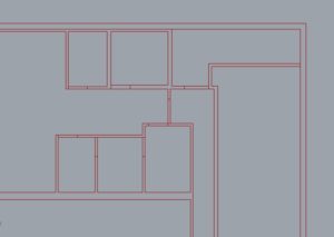
Here is the algorithm in action with a bunch of random line work. For floor plans, it is necessary that all door headers and wall lines connect to create closed geometry:
At this time the algorithm can’t handle regions with holes, as it shows in the video. It will select the boundary found in the positive y-direction from its position. For now this works for my use, as I rarely create rooms with holes in them. They certainly exist in architecture, but are typically found in programs with large lobbies / atria. In my current work, reflected ceiling plans with 24×24 or 24×48 acoustic tiles is common. I am writing an algorithm to find the optimal layout for this, which is essentially the selection of a single point to align the grid. Lighting requirements, symmetry, minimizing custom tile cuts and thin slices are the goals in this case. More to come…
Here is the python code that I wrote to find the boundary: Boundaries.py